

The Importance of High-precision 3D Inspection for Fixed Components of Large Hydraulic Equipment
The fixed components of large hydraulic equipment (such as 10,000-ton forging presses, extruders, and thick plate straightening machines) are typically the core carriers for maintaining the overall machine's rigidity and precision. These components include upper crossbeams, lower worktables, and column mounting seats, whose geometric accuracy directly determines the linear motion of hydraulic cylinder pistons, the repeatability of mold closing, and the uniformity of load distribution.
Under heavy-load and high-pressure operating conditions, even minor deviations in hole positions, coaxiality errors, or uneven reference surfaces in fixed components can lead to misalignment wear of moving pairs, hydraulic leaks, or even structural fatigue cracking. Therefore, conducting high-precision 3D dimensional inspection during manufacturing, assembly, and periodic maintenance is a critical process to ensure safe equipment operation and consistent product quality.
Inspection Requirements for 3D Measurement of Fixed Components of Large Hydraulic Equipment
The dimensions of such components often reach several meters or even up to 10 meters, with weights reaching dozens of tons. The main inspection items include:
① Positional tolerance and coaxiality of key hole systems
For example: positional tolerances between column mounting holes, main hydraulic cylinder mounting holes, and guide pin holes, as well as the coaxiality of multiple bearing holes along the same axis.
② Flatness and parallelism of mating end faces
For example: load-bearing mating surfaces between upper crossbeams and columns, or between worktables and bases, which require good contact stiffness.
③ Centering and perpendicularity of large planar surfaces and mounting slots
For example: symmetry of T-slots and locating keyways for mold installation relative to the equipment centerline, as well as the perpendicularity of the fixed component's reference surface to the main machine's axis.
Limitations of Traditional Inspection Methods
For these large-scale, heavy fixed components, traditional methods primarily rely on large Coordinate Measuring Machines (CMMs), laser alignment instruments, levels, inside micrometers, and piano wire combined with electrical measurement methods. However, these approaches have various limitations, such as:
① Inability to perform in-situ inspection: Components must be hoisted and transported to a CMM room, posing risks, requiring long auxiliary time, and preventing real-time feedback for assembly adjustments;
② Disordered measurement items: Hole system positions, coaxiality, and flatness require multiple instruments working together; reference transfer is cumbersome and prone to introducing cumulative errors;
③ Relatively low efficiency, reliance on manual labor, and high sensitivity to environmental factors: For coaxiality measurements with spans exceeding 10 meters, adjusting piano wires or alignment tubes is relatively time-consuming, and they are highly susceptible to temperature and airflow, making repeatability difficult to guarantee;
④ Measurement blind spots: Using levels or autocollimators to measure flatness of large planes involves segment stitching, making it difficult to cover local depressions near hole systems, and unable to establish a unified coordinate system linking the plane and hole system references.
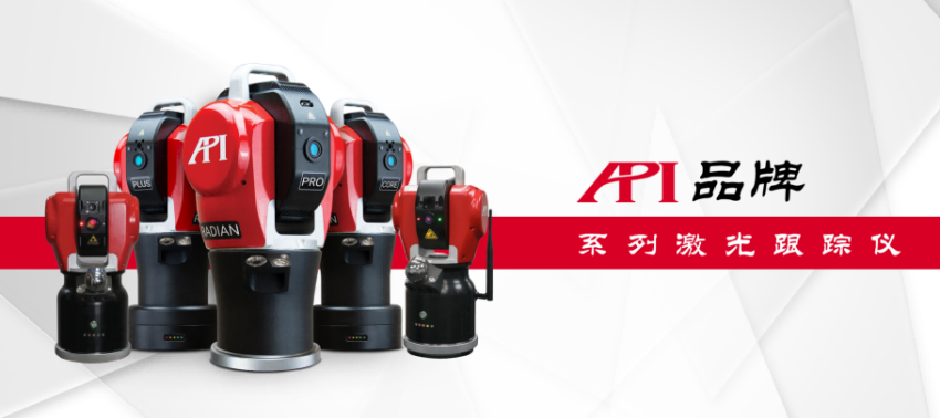
Figure 1: API Radian Series and iLT Series Laser Trackers
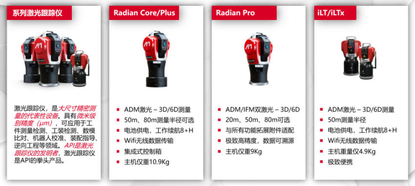
Figure 2: Introduction to API Laser Tracker Models
Application Advantages of API Laser Trackers
API laser trackers (such as the Radian series and iLTx series) meet the high-precision 3D inspection requirements for large hydraulic components. Their application advantages are mainly reflected in:
① Easy realization of large-range, high-precision 3D measurement: With a measurement radius exceeding 80 meters and micrometer-level spatial accuracy, it maintains a comprehensive uncertainty better than 0.1 mm even over spans of more than ten meters, directly satisfying position and coaxiality requirements;
② Full-element inspection under a unified datum: By using the tracker to establish a global coordinate system, all features such as holes, end faces, and slots can be measured in one go, avoiding datum conversion errors and achieving true 3D digital alignment;
③ Portability and support for on-site operations: The instrument features a highly integrated compact design, allowing it to be set up directly on workshop floors or equipment for in-situ measurement of heavy fixtures, enabling immediate acquisition of deviation data to guide grinding or assembly adjustments;
④ Dynamic tracking monitoring and hidden point measurement: Equipped with the vProbe hidden-point smart probe, it can quickly acquire features difficult for traditional tools to reach, such as deep holes and concave surfaces, without repeatedly moving parts; combined with the ActiveTarget dynamic target and STS six-axis sensor, it also easily achieves 3DoF and 6DoF dynamic measurements;
⑤ Real-time analysis and intelligent reporting: Measurement software displays 3D deviations in real time and automatically generates geometric tolerance reports for position, coaxiality, flatness, etc., significantly shortening inspection cycles.
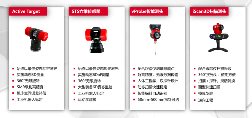
Figure 3: Introduction to Functional Expansion Accessories for API Laser Trackers
Measurement Site
Simply deploy the API laser tracker around the equipment and components to be measured, connect a laptop, and begin measurement.
During measurement, the operator holds a laser tracker target sphere (SMR) containing an internal prism. The laser tracker emits a laser beam to the center of the SMR and locks onto it. The operator touches the target sphere (or selects appropriate accessories such as vProbe, iScan3D, STS, or ActiveTarget based on needs) against the location to be measured. The API laser tracker then measures and collects the spatial coordinates of that point at an ultra-high sampling rate of 1000 Hz. The collected coordinate parameters are transmitted in real time to the measurement software on the laptop for subsequent analysis.
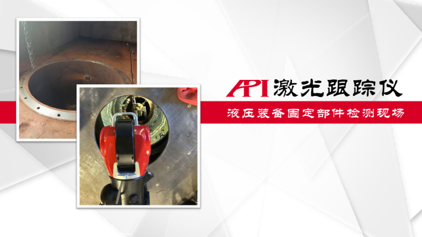
Figure 4: On-site Inspection of Fixed Components of Hydraulic Equipment Using API Laser Tracker
After all data has been measured, the software can use the acquired points to fit and construct corresponding lines, planes, and volumes. It can perform automatic calculations and analysis on required items and generate data reports as needed.
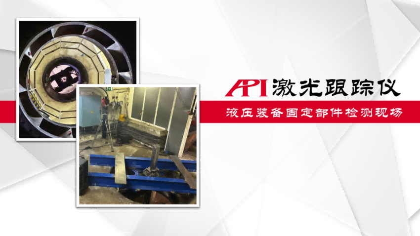
Figure 5: On-site Inspection of Fixed Components of Hydraulic Equipment Using API Laser Tracker
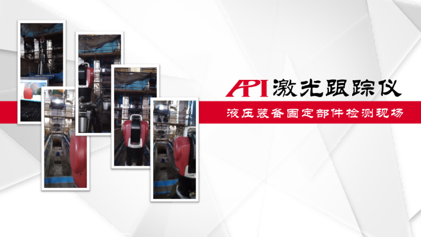
Figure 6: On-site Inspection of Fixed Components of Hydraulic Equipment Using API Laser Tracker
Summary
With its excellent performance, strong in-situ measurement capability, and efficient unified assessment of all elements, the API laser tracker has overcome the dilemma in traditional inspection of fixed components of large hydraulic equipment where efficiency and precision could not be balanced simultaneously. It makes the inspection of complex geometric tolerances such as hole pattern position, coaxiality, and end-face flatness real-time, intuitive, and reliable, not only ensuring assembly quality during major equipment overhauls but also providing an efficient means for digital inspection during the manufacturing phase.
相关新闻:
High-precision 3D Inspection of Fixed Components in Large Hydraulic Equipment API Laser Tracker App
The Importance of High-precision 3D Inspection for Fixed Components of Large Hyd
Surgical Robot Calibration and Accuracy Enhancement API Laser Tracker Application Solution
About Surgical RobotsWith the leapfrog development of modern manufacturing, robo
Yacht Maintenance 3D Measurement Solution API Laser Tracker Application Case
The Importance of Regular Yacht Maintenance and InspectionFor yachts, whether su
API exhibition preview: IMTS2026
API brand will participate in the IMTS2026 exhibition, which will be held at McC
Learn More:
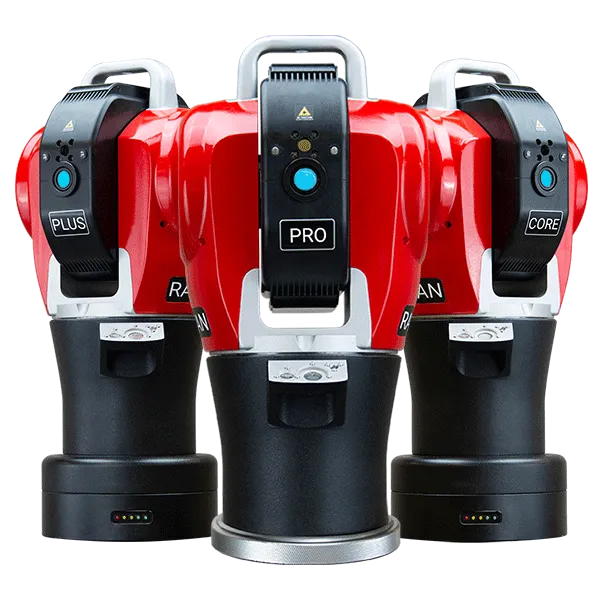
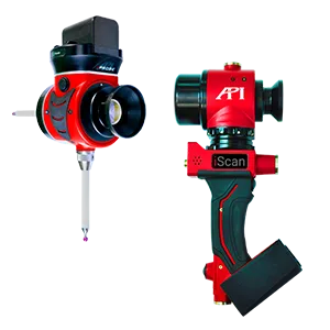
激光跟踪仪靶球&测头
Maximize laser tracker productivity with hand held and 激光跟踪仪主动靶标.
Learn More /laser-tracker-targets
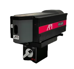
XD Laser CMM Calibration
The XD Laser is the only assessment system that can measure all 6 error parameters simultaneously in a single set-up
Learn More /xd-laser

API Reverse Engineering Service
Reverse engineering services include scan as-built parts to creation of a 3D digital point cloud and CAD Model.
Learn More /reverse-engineering/