


Measurement Background
The client is a large-scale manufacturer of wind turbine piles. Due to recent requirements from foreign project owners, measurements were needed for the geometry, dimensions, and form and position tolerances of flanges and pile sections. The measurement requirements demanded high precision within a large spatial range while also ensuring inspection efficiency.
After comparing multiple measurement solutions, it was decided to use the API Radian laser tracker for the measurements. The Radian laser tracker is a representative tool for precision metrology, and laser tracking technology has been widely applied in high-end manufacturing across various industries as well as academic research in scientific institutions. The Radian and iLT series laser trackers developed and manufactured by API feature excellent performance, stable operation, extreme portability, and ease of use, making them an outstanding solution for large-scale precision measurement.
Laser Tracker Measurement
When using a laser tracker for measurement, a retroreflector sphere must be placed on the surface of the object being measured. The laser tracker emits a laser beam toward the sphere; upon receiving the beam, the three reflective surfaces inside the sphere reflect the beam back into the laser tracker. The tracker can then determine the coordinates of the reflector by measuring two angles—elevation (EL) and azimuth (AZ)—as well as the radial distance. The EL and AZ angles are measured using encoders installed on the azimuth and elevation axes of the laser tracker.

Figure 1: API Radian Series / iLT Series Laser Trackers
If the tracker loses track of the retroreflector, a built-in high-definition camera located at the main unit head will locate the sphere and lock it within the field of view. Through this method, the tracker can quickly reacquire a lost target without any user assistance.
On-site Measurement
Based on the client's inspection requirements, API engineers performed the following measurements on the existing pile sections and flanges:
① The tested pile section had 168 flange holes, grouped in sets of four (totaling 42 groups), with measurements taken at fixed positions for each group of flange holes;
② The diagonal positions of the 42 groups corresponded pairwise, and the center-to-center distances between these holes were measured;
③ Flatness of the outer plane of the flange was measured;
④ Evaluation of whether the outer plane of the flange exhibited outward bulging.
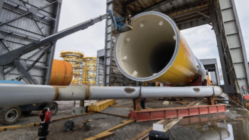
Figure 2: On-site Application Case Measurement
Measurement Data and Analysis of 42 Circles

Figure 3: Measurement Data and Analysis of 42 Circles
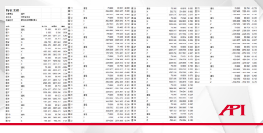
Figure 4: Flange Hole Measurement Data Analysis
Flange Face Flatness Measurement
The evaluation method for flatness is the minimum envelope method, which determines that when the distances from the two farthest points forming the envelope planes to the reference plane are equal, the distance between the two envelope planes represents the flatness measurement value (as shown in Figure51, where the value of d is the flatness measurement).
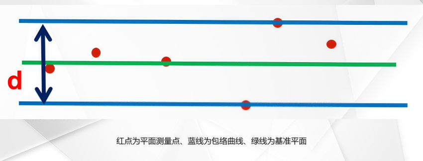
Figure 5: Schematic diagram of flatness measurement
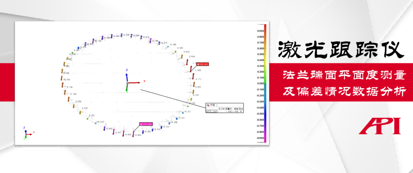
Figure 6: Flange face flatness measurement and deviation analysis
Flange hole diagonal length measurement
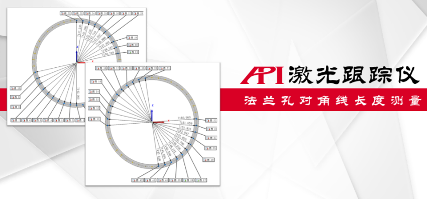
Figure 7: Data analysis of flange hole diagonal length measurement
Flange inward tilt measurement
During production, flange faces are permitted to have an inward tilt but not an outward flip; therefore, it is necessary to evaluate whether any points on the flange face have undergone an outward flip. By analyzing the deviation color map between measured points and the flange face, one can determine if an outward flip has occurred. Please refer to Figure 8: warm-colored straight lines extending upward represent outward flip measurement points, while cool-colored curves extending downward represent inward tilt measurement points.
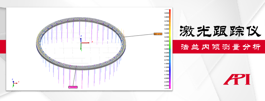
Figure 8: Schematic diagram of flange inward tilt measurement and data analysis
Coaxiality measurement of flanges on both sides
When measuring the coaxiality of flanges on both sides, the tracker can be placed inside the pile cylinder. First, use a target sphere to measure the cylindrical surface of one flange, and then proceed to measure the other side. During evaluation, calculate the coaxiality of the second side using the first side as the reference.
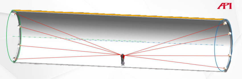
Figure 9: Schematic diagram of coaxiality measurement for flanges on both sides
Summary
Taking the inspection of wind turbine tower flanges in this case as an example, the large-scale, high-precision measurement capabilities of the API laser tracker fully meet the industry's demand for high-precision inspection of large components, achieving compatibility between wide-range coverage and high accuracy
相关新闻:
Comprehensive Accuracy Rapid Assessment and Diagnosis of CNC Machine Tools Application Case of API
Regarding Rapid Testing of CNC Machine ToolsTime cost holds significant importan
Non-contact High-precision 3D Inspection of Construction Machinery Components API 9D LADAR (9D LiDA
The Importance of 3D Inspection for Construction Machinery ComponentsConstructio
High-Efficiency 3D Inspection of Large Steel Mill Equipment Application Case of API Laser Tracker
Importance of 3D Inspection for Large Steel Mill EquipmentLarge steel mill equip
High-precision 3D Inspection of Textile Machinery Roller Components API Laser Tracker Application C
The Importance of 3D Inspection for Textile Machinery RollersRoller components a
Learn More:
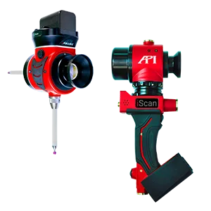
激光跟踪仪靶球&测头
Maximize laser tracker productivity with hand held and 激光跟踪仪主动靶标.
Learn More /laser-tracker-targets
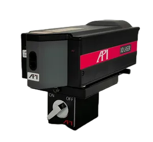
XD Laser CMM Calibration
The XD Laser is the only assessment system that can measure all 6 error parameters simultaneously in a single set-up
Learn More /xd-laser

API Reverse Engineering Service
Reverse engineering services include scan as-built parts to creation of a 3D digital point cloud and CAD Model.
Learn More /reverse-engineering/