

Importance of 3D Inspection for Large Steel Mill Equipment
Large steel mill equipment serves as the core carrier of steel production, primarily including hot rolling mills, cold rolling mills, slab continuous casters, straighteners, large gearboxes, and various roller conveyor systems. Such equipment is characterized by heavy individual mass (ranging from tens to hundreds of tons per unit), large structural dimensions (total rolling line length reaching hundreds of meters, single-unit stand height exceeding 10 meters), and severe operating conditions (high temperature, heavy load, high speed, strong impact).
Its geometric accuracy directly determines product dimensional precision, surface quality, and equipment operational stability. For instance, parallelism and perpendicularity deviations in the window face of a rolling mill stand are directly transmitted to the roll gap, causing excessive transverse thickness variation in the strip; arc accuracy deviations in the arc segment roller series of a continuous caster can lead to bulging or internal cracking of the ingot.
Therefore, implementing high-precision 3D inspection for large equipment is not only an essential step for installation commissioning and maintenance but also the foundation for achieving intelligent production line control and ensuring the quality of high-value-added steel products.
Inspection Requirements
The 3D inspection content for large steel mill equipment covers static geometry, assembly relationships, and dynamic datum transfer, mainly including:
① Rolling mill stand geometric accuracy: flatness of both sides of the stand window, mutual parallelism, perpendicularity of the window to the rolling centerline, and parallelism and elevation difference between upper and lower crossbeams;
② Coaxiality and levelness of the roll system: coaxiality of roll necks, horizontal levelness, and crossing angle of roll body generatrices for work rolls, backup rolls, and intermediate rolls;
③ Arc accuracy of continuous casting arc segment roller series: radial deviation of each roll axis relative to the theoretical arc, parallelism of adjacent roll axes, and spatial coplanarity of the entire roller series;
④ Perpendicularity of end faces to the axis for large rotating components: such as the perpendicularity of end faces to the axis for coiler drums, flying shear rotors, and gear shafts;
⑤ Installation datum transfer between multiple devices: such as axial alignment between rolling mill stands and drive motors/gearboxes, and elevation and parallelism between roller conveyors and the rolling line;
⑥ Foundation settlement and deformation monitoring: periodic verification of the position of base plates and anchor bolt holes for key equipment.
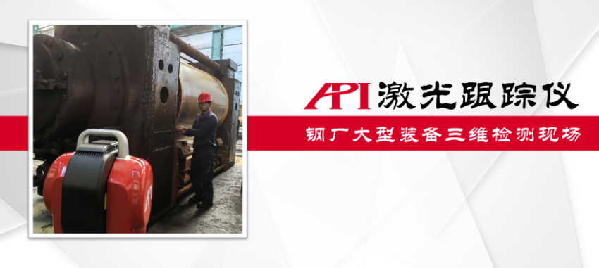
Figure 1: On-site 3D Inspection of Large Steel Mill Equipment Using API Laser Tracker
Inspection Challenges
The above inspection contents impose extremely high requirements on measurement methods, with main challenges as follows:
① Large measurement range requiring兼顾local precision: The span of a single rolling mill stand can reach 2–4 meters, and the baseline transfer distance across the entire rolling line can extend to dozens of meters, requiring the detection equipment to maintain sub-millimeter乃至tens-of-microns-level precision over distances of tens of meters;
② Harsh on-site environment with numerous interference factors: Strong vibration, significant temperature gradients, and severe dust and oil pollution exist at the steel mill site. Traditional optical instruments are easily affected by thermal turbulence and contamination, resulting in poor measurement stability;
③ Complex shapes and poor accessibility of measured objects: Spaces inside the stand window, beneath the roll system, and within roller conveyor gaps are narrow, preventing direct observation by instruments. Moreover, large components are difficult to rotate or move, necessitating multi-angle measurements in situ;
④ Measurement data requires rapid alignment with design baselines: Large equipment inspection often involves comparing measured points against CAD models or theoretical axes, requiring the measurement system to possess robust coordinate transformation and data processing capabilities; otherwise, manual fitting is extremely inefficient;
⑤ Multi-point dynamic or semi-dynamic detection is difficult: For instance, runout during roll system rotation or face wobble during coiler operation are challenging for traditional static measurement methods to capture effectively.
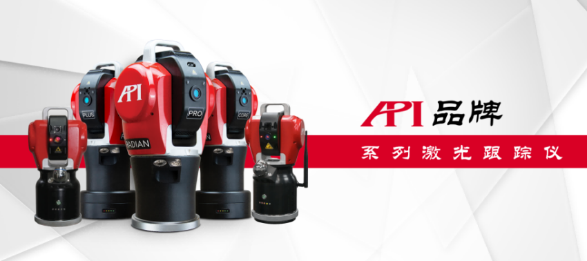
Figure 2: API Radian and iLT Series Laser Trackers
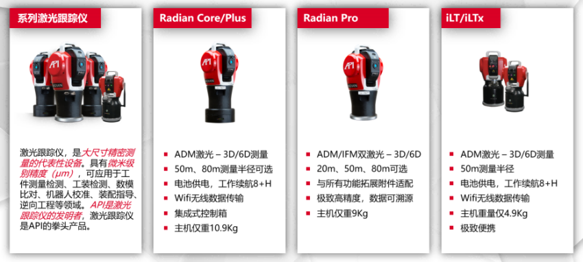
Figure 3: Brief Introduction of Functions for Various API Laser Tracker Models
API Laser Tracker Inspection Solution
API laser trackers (currently available in the Radian and iLT series) are portable large-scale 3D coordinate measuring systems. Their core principle involves real-time tracking of the spatial position of a retroreflector (SMR) through laser interferometric ranging (or absolute laser ranging) combined with two-axis precision turntable angle measurement. The measurement range can exceed a diameter of 160 meters, while maintaining micrometer-level spatial measurement accuracy.
Its main performance features include: a large-scale measurement range (diameter up to 160 m), micrometer-level comprehensive measurement accuracy, ultra-high sampling rate (up to 1000 points/second), wireless data transmission, built-in leveler with automatic environmental compensation, stable operation under various harsh conditions, compatibility with most commercial measurement software, rapid integration into existing customer measurement systems, and support for CAD comparison, geometric fitting, coordinate transformation, and automated report generation.
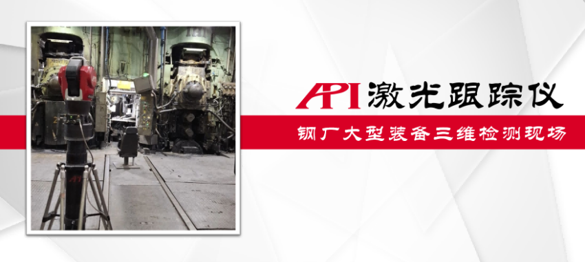
Figure 4: On-site 3D Inspection of Large Equipment at Steel Mill Using API Laser Tracker
For the 3D inspection of large equipment at steel mills, the specific implementation plan is as follows:
(1) Parallelism and Perpendicularity Inspection of Stand Window Faces
Set up the API laser tracker on a stable foundation on either the operator side or drive side of the rolling mill, establishing a measurement coordinate system with the rolling centerline as the X-axis, horizontal and vertical directions as the Y-axis, and the vertical direction as the Z-axis. Collect 20–40 SMR points in a grid pattern on each of the four inner surfaces of the stand window (operator side top/bottom, drive side top/bottom). Use the software's plane fitting function to calculate the flatness of each surface; then compute the parallelism of the window faces by calculating the angles between pairs of planes. Evaluate the perpendicularity of each window face relative to the rolling centerline (fitted through the centers of bearings on both sides or embedded reference points) as the baseline. Due to the API tracker's characteristics of large range and high precision, a single station can cover the entire stand window without repositioning, effectively avoiding stitching errors associated with multi-station setups.
(2) Coaxiality Inspection of Roll System
Attach the SMR sequentially to touch and measure the upper, lower, left, and right generatrix positions of each roll neck, or use an SMR fixture spanning the roll neck to simultaneously acquire end points of the axis. During measurement, slowly rotate the roll to collect SMR coordinates at different angular positions. The API tracker records data rapidly at a maximum sampling rate of 1000 Hz. Circle fitting yields the center of each cross-section of the roll necks, followed by axis fitting using multiple section centers to calculate the coaxiality deviation between roll axes.
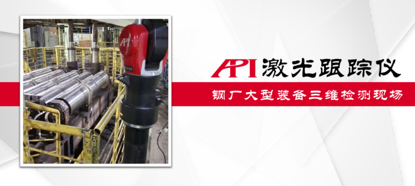
Figure 5: On-site 3D Inspection of Large Equipment at Steel Mill Using API Laser Tracker
(3) Arc Profile Inspection of Continuous Casting Sector Roll Rows
Set up the tracker on a reference platform on one side of the sector. Establish a polar coordinate system with the theoretical arc center of the casting machine as the origin. Collect 6–9 SMR points on each roll (at both ends and the middle), keeping the rolls stationary during measurement. The software performs optimal fitting of the measured point cloud against the theoretical arc model (imported from CAD) and outputs radial deviations of each roll axis, parallelism between adjacent roll axes, and coplanarity of the entire roll row. The API tracker's exceptionally large measurement radius (up to over 80 m) allows the entire sector (length up to 20 m) to be measured from a single station, avoiding cumulative errors caused by multiple repositionings.
(4) Dynamic End Face Perpendicularity Inspection of Large Rotating Components
Install SMR bases on the edge of the coiler drum or flying shear drum end face and start the equipment rotating at low speed. Set the tracker to scan measurement mode and continuously record the SMR trajectory at a rate of 1000 points/second. The software fits the trajectory points to a plane and calculates the angle between the end face normal vector and the rotation axis (derived from cylinder fitting of the journal surface), which represents the end face perpendicularity error. The advantage of this method is that dynamic measurement accurately reflects actual end face runout under operating conditions, avoiding false deviations caused by gravity or support in static measurements.
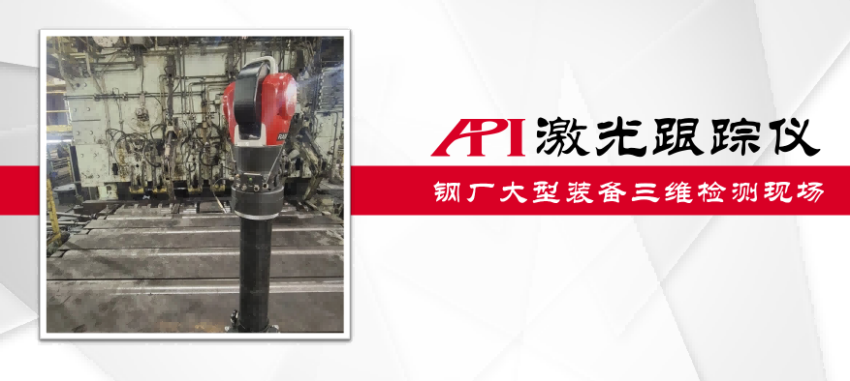
Figure 6: On-site 3D Inspection of Large Equipment at Steel Mill Using API Laser Tracker
(5) Axis Alignment of Multiple Devices and Transfer of Installation Baselines
The vProbe hidden-point smart probe, used in conjunction with the API tracker, is capable of measuring anchor bolt holes, reference pin holes, and other features at concealed locations. Local coordinate systems are established separately on the rolling mill frame, gearbox, and motor base, which are then unified into the tracker's coordinate system via common reference points. The software directly outputs parallelism, coaxiality, and elevation differences between various axes, and generates adjustment recommendations. The baseline transfer for the entire rolling line (up to 100 meters in length) can be achieved by setting turn-around reference points at several key locations.
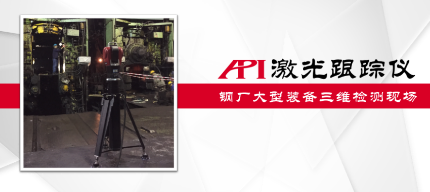
Figure 7: On-site 3D inspection of large-scale equipment in a steel plant using an API laser tracker
Summary of the solution's advantages:
The API laser tracker covers all measurement needs ranging from a few meters to over one hundred meters with a single device, eliminating the need to change instruments or frequently reposition; the high sampling rate of the API tracker, combined with absolute distance measurement capabilities and meteorological station support, ensures stable data output even in environments with strong vibration and temperature fluctuations; when paired with API MeasurePro measurement software or mainstream market solutions (such as SpatialAnalyzer, Polyworks, Metrolog, Verisurf, etc.), real-time comparison between measured points and CAD models can be performed, automatically generating geometric error reports and significantly reducing on-site downtime. Compared to traditional levels, alignment tools, and wire-stretching methods, detection efficiency is increased by 3 to 5 times or more, while offering higher measurement accuracy and stronger data traceability.
Conclusion
Three-dimensional inspection of large-scale equipment in steel plants is a critical step in ensuring production line precision and product quality, characterized by large object dimensions, complex environments, and high accuracy requirements. Leveraging its ultra-long range, high precision, high sampling rate, strong environmental adaptability, and intelligent software platform, the API laser tracker can efficiently complete various inspection tasks including rolling mill frames, roll systems, arc sections, rotating components, and installation baselines. It achieves wide-area coverage from a single station, dynamic face perpendicularity measurement, hidden-point measurement, and long-distance baseline transfer, providing reliable technical means for steel enterprises to reduce maintenance downtime and enhance digital equipment management. With the rapid development of the steel industry towards intelligent manufacturing, large-scale precision 3D measurement technology, represented by the API laser tracker, is playing an increasingly important role in full lifecycle equipment management.
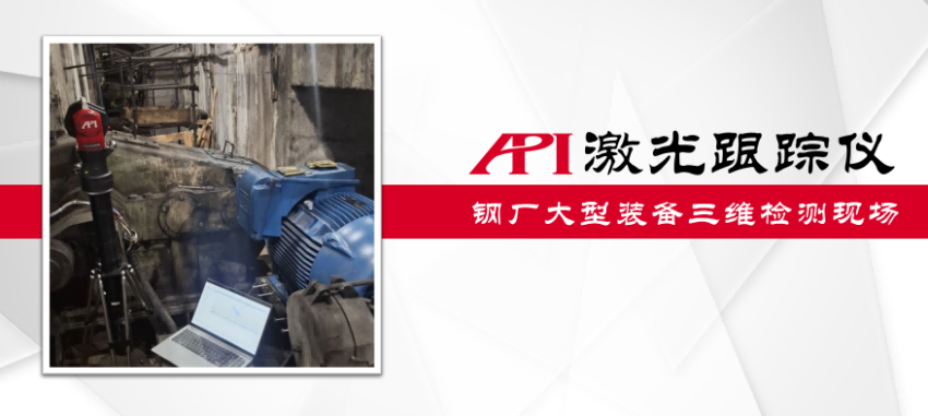
Figure 8: On-site 3D inspection of large-scale equipment in a steel plant using an API laser tracker
About API
The API brand was founded by Dr. Kam Lau in Rockville, Maryland, USA in 1987. As the inventor of the laser tracker and holder of multiple patents in globally leading measurement technologies, API is a leader in the field of precision measurement technology. Since its inception, API has been dedicated to the research, development, and production of precision measurement instruments and high-performance sensors for the machinery manufacturing sector. Its products are widely applied in advanced manufacturing fields worldwide and hold a leading position in high-precision standards for coordinate metrology and machine tool performance testing.
相关新闻:
Comprehensive Accuracy Rapid Assessment and Diagnosis of CNC Machine Tools Application Case of API
Regarding Rapid Testing of CNC Machine ToolsTime cost holds significant importan
Non-contact High-precision 3D Inspection of Construction Machinery Components API 9D LADAR (9D LiDA
The Importance of 3D Inspection for Construction Machinery ComponentsConstructio
High-Efficiency 3D Inspection of Large Steel Mill Equipment Application Case of API Laser Tracker
Importance of 3D Inspection for Large Steel Mill EquipmentLarge steel mill equip
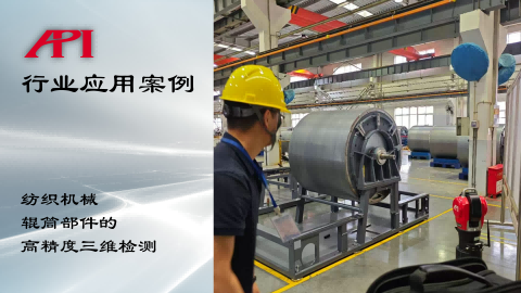
High-precision 3D Inspection of Textile Machinery Roller Components API Laser Tracker Application C
The Importance of 3D Inspection for Textile Machinery RollersRoller components a
Learn More:
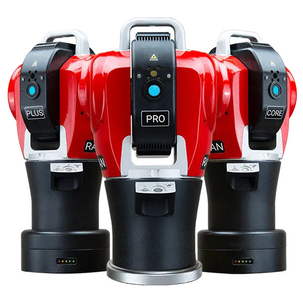
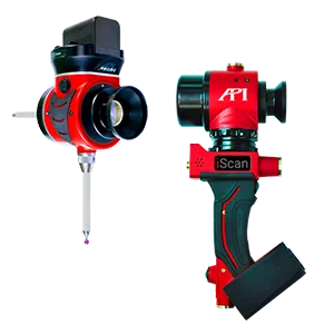
激光跟踪仪靶球&测头
Maximize laser tracker productivity with hand held and 激光跟踪仪主动靶标.
Learn More /laser-tracker-targets
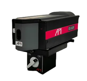
XD Laser CMM Calibration
The XD Laser is the only assessment system that can measure all 6 error parameters simultaneously in a single set-up
Learn More /xd-laser
API Reverse Engineering Service
Reverse engineering services include scan as-built parts to creation of a 3D digital point cloud and CAD Model.
Learn More /reverse-engineering/