


The Importance of 3D Inspection for Textile Machinery Rollers
Roller components are critical rotating parts in textile machinery responsible for tasks such as yarn or fabric traction, winding, pressing, and guiding. In spinning, weaving, dyeing, and finishing equipment, the geometric accuracy of rollers directly affects tension uniformity, operational stability, fabric width quality, and the vibration and noise levels of the equipment. If a roller exhibits coaxiality deviation, out-of-cylindricity beyond tolerance, or abnormal face runout, it can easily lead to fabric misalignment, tension fluctuations, uneven winding density, and even early bearing wear and increased整机vibration.
Therefore, implementing high-precision 3D inspection for textile machinery roller components not only verifies machining and assembly quality but also provides reliable data for equipment commissioning, fault diagnosis, and reverse repair. Especially against the backdrop of continuously developing high-speed and wide-width textile equipment, even minor deviations in roller geometric errors can be amplified into significant process defects, making high-precision inspection particularly important.
Content Requiring Inspection
Three-dimensional inspection of textile machinery roller components mainly includes the following contents:
① Coaxiality Inspection: Measure the coaxiality of the bearing mounting journals at both ends relative to the reference axis to avoid additional bending moments and vibrations caused by non-coaxial supports at both ends.
② Cylindricity Inspection: Evaluate the cylindricity error of the roller working surface to ensure uniform contact characteristics in both the circumferential and axial directions, avoiding local wear and uneven fabric tension.
③ Radial Runout and Face Runout Inspection: Measure the runout values of the roller working surface and end faces to determine whether periodic swaying or axial movement occurs during roller rotation.
④ Axial Positioning Dimensions and Spatial Position of Critical Sections: Obtain the spatial coordinates of each shoulder, roller edge, and mounting reference plane to verify the axial dimension chain and assembly positional relationships.
Regarding inspection precision requirements, for high-precision textile machinery rollers, the measurement uncertainty of coaxiality and cylindricity errors, face runout and radial runout, and key axial positioning dimensions must all be controlled within 0.05 mm.
Limitations of Traditional Inspection Methods
Traditional inspection of textile machinery rollers often employs tools such as measuring platforms, dial indicators, calipers, and micrometers. Although these methods are simple to operate and low-cost, they also have relatively obvious limitations:
First, it is difficult to achieve an overall three-dimensional evaluation. Traditional methods can only measure several local cross-sections or runout in a single direction, failing to fully capture the true attitude of the roller axis in space and the error distribution across its entire length.
Second, establishing a datum is relatively difficult. For rollers with a large length-to-diameter ratio and long span, when using V-blocks and platforms for alignment, the datum axis itself is easily affected by support positions, platform flatness, and self-weight deformation of the roller, making measurement repeatability hard to control.
Third, measurement accuracy is significantly influenced by human factors. Steps such as reading dial indicators, fixing indicator stands, and selecting measurement points rely heavily on operator experience, making data consistency difficult to guarantee.
Fourth, measurement efficiency is relatively low, and digitalization level is not high. Traditional methods struggle to quickly generate three-dimensional error analysis and visualized reports, which is unfavorable for comparison with design models and quality traceability.

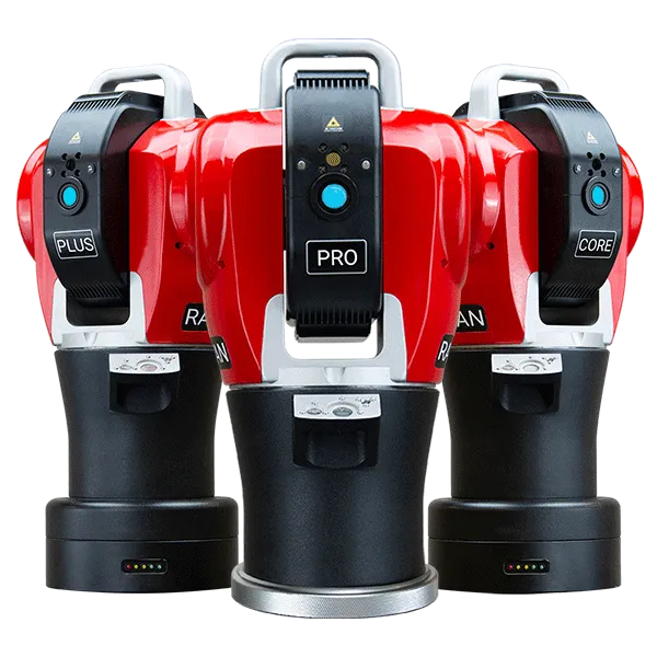
Figure 1: API Series Laser Trackers
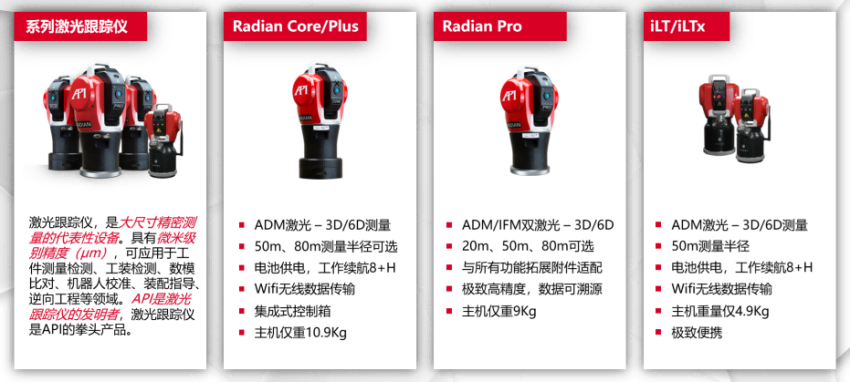
Figure 2: Performance Overview of Various API Laser Tracker Models
API Laser Tracker Inspection Solution
The API laser tracker provides an effective solution for high-precision 3D inspection of textile machinery roller components, leveraging its wide measurement range, high accuracy, and portable spatial coordinate measurement capabilities.
This solution offers the following prominent advantages:
First, high precision. The API laser tracker enables micrometer-level spatial coordinate measurement, meeting the requirements for measurement uncertainty in projects such as roller coaxiality, cylindricity, and runout.
Second, a large measurement range. Textile machinery rollers often reach lengths of 1–3 m or more; however, the laser tracker's working range can extend to tens of meters, allowing for the complete measurement of an entire roller without stitching.
Third, it supports in-situ measurement. Rollers can be inspected while maintaining their actual installed state or post-machining support state, avoiding additional deformation caused by disassembly and lifting, thereby yielding measurement results closer to real-world operating conditions.
Fourth, high digitization. Coupled with measurement software, it can acquire 3D point clouds in real time, fit cylinders and axes, calculate geometric tolerances, and automatically generate visualized measurement reports.
Fifth, flexible operation. Through contact measurement using target spheres and targets, it can quickly obtain spatial coordinates for different features such as the roller surface, journal, and end face, making it suitable for complex on-site environments.
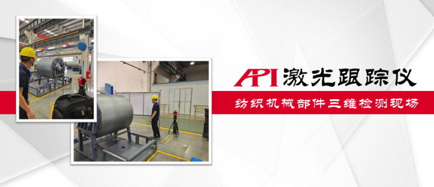
Figure 3: On-site 3D Inspection of Textile Machinery Components Using API Laser Tracker

Figure 4: On-site 3D Inspection of Textile Machinery Components Using API Laser Tracker
Measurement Site
At the inspection site of a textile machinery manufacturing enterprise, an engineer is using an API laser tracker to perform precision inspection on a drafting roller of a textile machine.
First, the roller is stably supported, and the laser tracker is set up at a location with good line-of-sight near the roller. Once the tracker is fixed on a tripod, connected to a computer, and powered on, measurement begins immediately. Environmental errors on-site (such as temperature, air pressure, humidity, etc.) are automatically identified and compensated for by the tracker's "Weather Station" system.
Upon starting the measurement, the operator holds a target sphere and sequentially acquires multiple circumferential section points along the bearing journal at one end of the roller, collecting 8–12 points per section (or according to specific needs); subsequently, the same measurement is performed on the journal at the other end.
For the central working surface of the roller, a cross-section is taken approximately every 200 mm (or according to needs) along the axial direction, with a ring of surface points collected for each section. For the end faces, multiple points are collected along the circumferential direction to calculate end-face runout and axial dimensions. All measured points are transmitted in real time to the measurement software, which automatically fits circles for each section and the overall cylinder axis, and calculates coaxiality of journals at both ends, cylindricity of the roller surface, radial circular runout, and end-face runout.
After measurement, the software directly generates a report containing measured values, deviation directions, and tolerance judgments. The entire measurement process can be completed within 30 minutes, significantly improving efficiency compared to traditional platform inspections.
Summary
Geometric precision of textile machinery roller components has a significant impact on overall machine performance and fabric quality. Leveraging its high-precision spatial coordinate measurement capability combined with portability, wide range, and digital advantages, the API laser tracker can efficiently and reliably complete critical inspection items such as roller coaxiality, cylindricity, runout, and axial positioning dimensions. This solution overcomes issues associated with traditional inspection methods, including localized measurement, difficulty in establishing datums, and poor data consistency, providing strong support for quality control, assembly commissioning, and process improvement of textile machinery rollers.
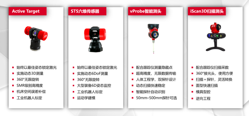
Figure 5: Introduction to Functional Expansion Accessories for API Laser Tracker
More Expansions
In addition to the method demonstrated in this case study, which uses a target ball for non-contact measurement of the object under test, API has developed a series of laser tracker functional expansion accessories based on various field application requirements:
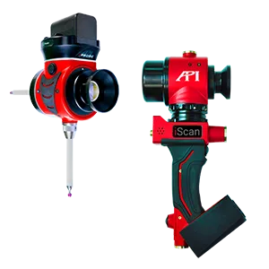
√ vProbe Smart Probe - Enables precise measurement of deep holes and hidden points;
√ iScan3D Smart Probe - Rapidly acquires point cloud data via line laser scanning;
√ ActiveTarget Active Target - Motor-driven with 360° wireless rotation in the horizontal plane; actively locks onto the laser tracker's beam in real-time, maintaining lock and ensuring smooth measurement even during high-speed and large-angle movements;
√ STS Six-Axis Sensor - Enables static and dynamic measurement of 6DoF (six degrees of freedom) data;
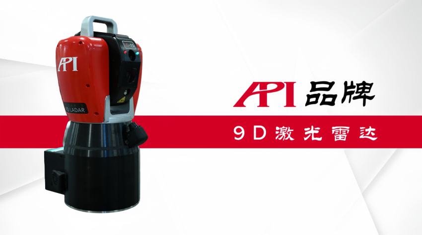
Figure 6: API 9D Laser Tracker
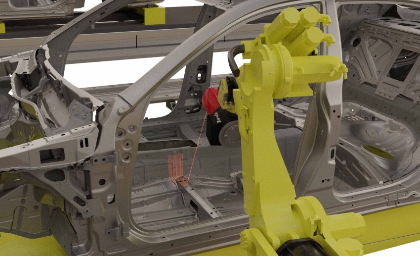
Figure 7: Schematic Diagram of API 9D Laser Tracker Operation Mode
Furthermore, the API 9D Laser Tracker system achieves micrometer-level spatial measurement accuracy in non-contact measurement applications without the need for cooperative targets. Please follow the official API website and major media platforms for the latest information.
相关新闻:
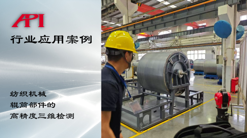
High-precision 3D Inspection of Textile Machinery Roller Components API Laser Tracker Application C
The Importance of 3D Inspection for Textile Machinery RollersRoller components a
High-precision 3D Inspection of Fixed Components in Large Hydraulic Equipment API Laser Tracker App
The Importance of High-precision 3D Inspection for Fixed Components of Large Hyd
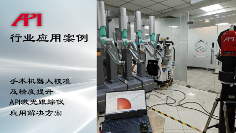
Surgical Robot Calibration and Accuracy Enhancement API Laser Tracker Application Solution
About Surgical RobotsWith the leapfrog development of modern manufacturing, robo

Yacht Maintenance 3D Measurement Solution API Laser Tracker Application Case
The Importance of Regular Yacht Maintenance and InspectionFor yachts, whether su
Learn More:
激光跟踪仪靶球&测头
Maximize laser tracker productivity with hand held and 激光跟踪仪主动靶标.
Learn More /laser-tracker-targets
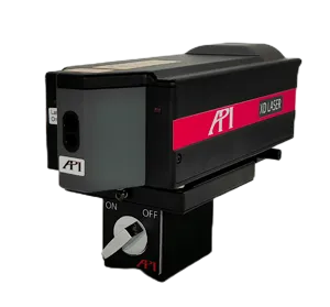
XD Laser CMM Calibration
The XD Laser is the only assessment system that can measure all 6 error parameters simultaneously in a single set-up
Learn More /xd-laser

API Reverse Engineering Service
Reverse engineering services include scan as-built parts to creation of a 3D digital point cloud and CAD Model.
Learn More /reverse-engineering/