


The Importance of Regular Yacht Maintenance and Inspection
For yachts, whether super sailing vessels or motorboats, long-term navigation in complex and variable marine environments subjects them to continuous wind and wave impacts, engine vibration, salt spray corrosion, and thermal expansion/contraction caused by day-night temperature differences. These persistent loads can cause minute deformations and positional drifts in the hull structure and propulsion system that are difficult to detect with the naked eye.
Once shaft alignment deviates, bases develop micro-tilts, or rudder post hole coaxiality is lost, it directly leads to abnormal bearing wear, increased vibration, higher fuel consumption, and even transmission system failure, severely compromising navigational safety and the riding experience.
From the perspective of 3D inspection, a yacht's reliability is built upon the geometric precision of its critical mechanical and structural components. These spatial geometric relationships are not isolated dimensions but rather constitute a rigorous 3D tolerance system involving "coaxiality," "flatness," "positioning," and "perpendicularity." Regular high-precision 3D maintenance measurements enable the timely detection of shaft deflection, base deformation, and appendage installation deviations, eliminating faults at their inception and providing scientific data support for the yacht's continued safe navigation.
Therefore, introducing advanced portable 3D measurement methods to implement condition-based precise maintenance has become an important trend in the management and maintenance of high-end yachts.
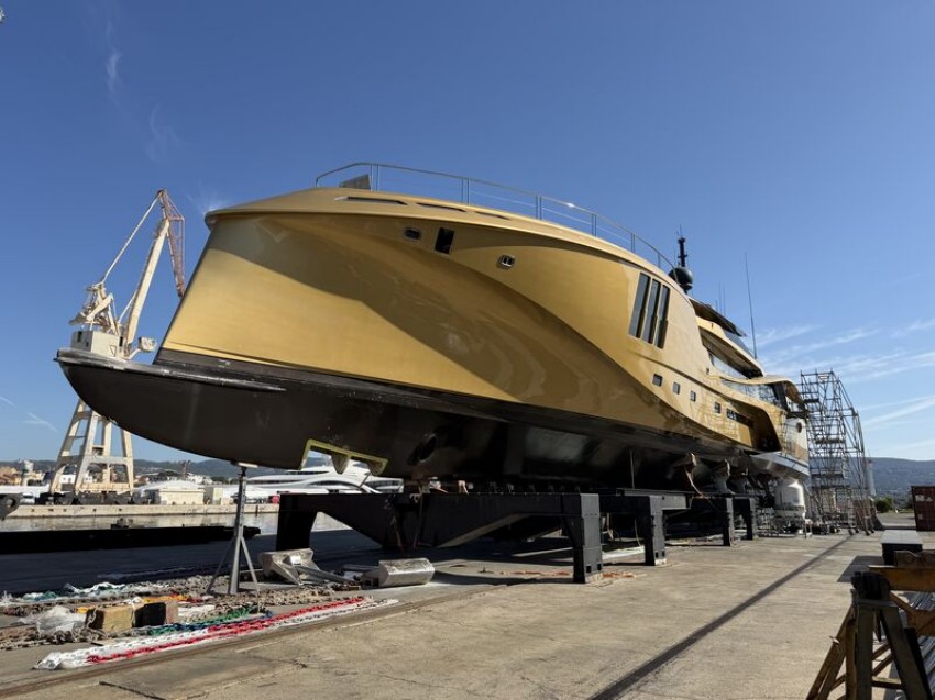
Figure 1: The yacht to be inspected in this case
Inspection Content
During the 3D inspection of a yacht, the core content requiring precise measurement typically includes:
① Propulsion Shaft System Straightness and Coaxiality: Covers the axial coaxiality between intermediate shafts, stern tubes, main engine output shafts, and gearbox output flanges, as well as centerline alignment deviations among various bearing housings;
② Propeller Blade Installation Accuracy: Detection of blade pitch angles, relative positioning of blades to the hub, and uniformity of gaps between the outer edges of installed blades and the inner walls of the hull tunnel or brackets;
③ Rudder System Bearing Hole Coaxiality and Perpendicularity: Measuring the perpendicularity of the line connecting the centers of upper and lower rudder post bearing holes to the ship's baseline, as well as coaxiality deviations between bearing holes, ensuring smooth steering without binding;
④ Main Engine and Gearbox Base Flatness and Positioning: Detecting flatness of elastic bases and rigid mounting surfaces, and verifying 3D coordinate deviations of base bolt holes relative to the theoretical centerline of the shaft system;
⑤ Monitoring Deformation of Critical Hull Structures: Conducting spatial point cloud comparison or feature point measurement on key areas such as decks, bulkheads, stiffeners, mast pedestals, and stabilizer fin bases to monitor overall deformation trends after prolonged use;
⑥ Symmetry of Multi-functional Appendage Installation: Including symmetry relative to the ship's centerline and installation angles of appendages such as bilge keels, anti-sway plates, and strakes, ensuring proper navigation posture and hydrodynamic performance;
⑦ Verification of Large Compartment and Interface Locations: Detecting 3D positioning of precision assembly interfaces such as engine room skylights, hatch cover hinge holes, and radar mast flanges to provide accurate references for subsequent work.

Figure 2: API Radian Series and iLT Series Laser Trackers
Limitations of Traditional Inspection Methods
Prior to the widespread adoption of laser measurement technology, shipyards and repair bases typically relied on traditional methods such as wire plumb lines, straightedges, inside micrometers, dial indicators, and optical theodolites for 3D yacht inspections. Although these methods have been used for many years, they reveal multiple shortcomings when faced with the increasingly compact engine room layouts of modern yachts and higher precision requirements:
① High sensitivity to human and environmental factors: The steel wire method relies on the straightness of the wire. However, self-weight deflection over long distances, wind-induced vibration, temperature fluctuations, and personnel reading habits can introduce non-negligible measurement errors;
② Difficulty in achieving 3D spatial measurement: Dial indicators and feeler gauges only provide local relative runout, making it difficult to establish a global coordinate system or intuitively determine the true angular misalignment and offset of the shafting in space. When assessing combined "pitch" and "yaw" errors, traditional methods are often inadequate;
Low measurement efficiency requiring repeated disassembly: Measuring base flatness often requires hoisting out the main engine for repeated scraping and calibration with a surface plate and level, which is time-consuming. Once deviations are found, readjustment and re-measurement are required, leading to a repetitive process that is hard to schedule;
④ Difficult baseline transfer: Large yachts can be dozens of meters long. Transferring the axis baseline from the engine room bottom to the stern shaft hub and upper deck structures using traditional optical instruments requires multiple station setups, resulting in significant cumulative errors;
⑤ Insufficient data integrity and lack of visual reporting: Only discrete readings can be recorded, preventing the formation of a comprehensive 3D deviation color map. This makes post-hoc analysis and tracing difficult, hindering full-lifecycle digital management.
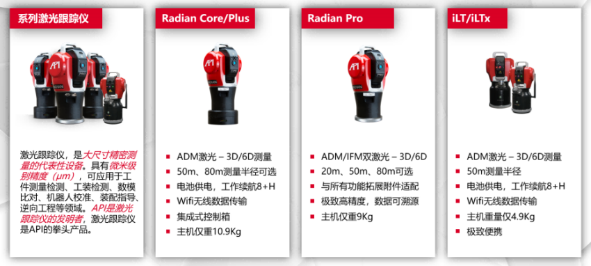
Figure 3: Performance Overview of API Laser Tracker Models
API Laser Tracker Measurement Solution
Addressing the urgent need for spatial geometric accuracy and efficient operations in yacht maintenance, the API laser tracker provides a 3D measurement solution that combines large range with high precision.
The API Radian and iLT series laser trackers utilize efficient ADM lasers (the Radian Pro model integrates both IFM and ADM lasers), paired with high-precision dual-axis angle encoders. They can capture 3D coordinates of spatial points in real-time, offering a measurement radius exceeding 80 meters and micron-level accuracy. Their portable design and flexible setup allow measurements to be conducted directly in dry docks, harbors, or workshops without hoisting the main engine or other large components, truly enabling "in-situ maintenance with dynamic guidance."
In practical application workflows: The measurement engineer first sets up the API laser tracker at a stable location in the engine room or stern, establishing a workpiece coordinate system covering the entire propulsion system using common reference points. Subsequently, by touching the inner walls, planes, and journals of characteristic features such as intermediate bearing housings, stern tube flanges, and the main engine output end with a handheld SMR, the software acquires spatial points in real-time and automatically calculates cylinders, planes, and center points.
The shaft alignment interface intuitively displays horizontal and vertical deviations of the fore and aft flanges via line graphs and 3D models, while base flatness is presented as a color-coded topography map. During adjustment, the laser tracker can activate dynamic tracking mode to display offset values in real-time, guiding technicians to eliminate deviations one by one using jacks and shims until all indicators fall within acceptable limits. For hidden rudder bearing holes, complete data can be easily obtained by combining station transfers or using the vProbe hidden-point intelligent probe.
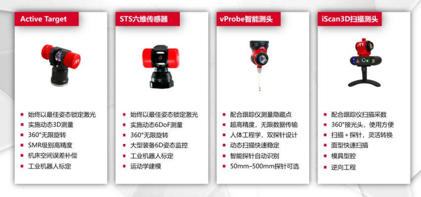
Figure 4: Introduction to API Laser Tracker Accessories
Compared to traditional methods, the advantages of the API laser tracker are significant:
① Order-of-magnitude improvement in accuracy: Concerns regarding wire sag or manual centering errors are eliminated. Data baselines are stable and reliable, enabling angular resolution at the arc-second level for parameters such as flange face angularity;
② Significant efficiency enhancement: A comprehensive maintenance measurement involving shaft alignment, base flatness, and rudder hole coaxiality might require days of iterative adjustments using traditional methods, whereas adjustments guided by the laser tracker typically take only a few hours, increasing overall efficiency by over 60%;
③ Dynamic adjustment and visualization: Real-time deviation display enables "adjust-and-check" operations, making them intuitive and significantly reducing trial-and-error attempts. After measurement, a single click generates a richly illustrated 3D inspection report, providing shipowners and surveyors with highly credible quality documentation;
④ Adaptability to complex sites: The API laser tracker integrates a weather station system that automatically identifies and compensates for environmental errors caused by temperature, humidity, and air pressure. Combined with its compact and lightweight design, it performs effortlessly even in cramped, stuffy engine rooms and supports single-person operation;
⑤ Full-lifecycle digital twin: Measurement data from each maintenance session is retained, forming a geometric status archive for the yacht. Long-term comparison allows monitoring of hull and shaft aging deformation patterns, shifting maintenance from "reactive repair" to "predictive maintenance."
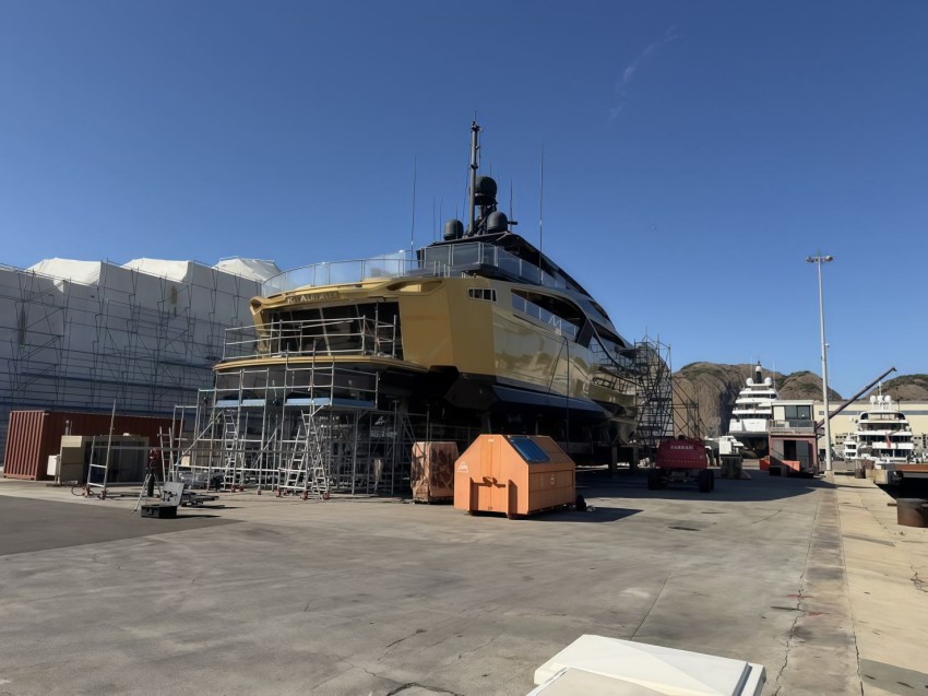
Figure 5: Measurement Site of This Case Study
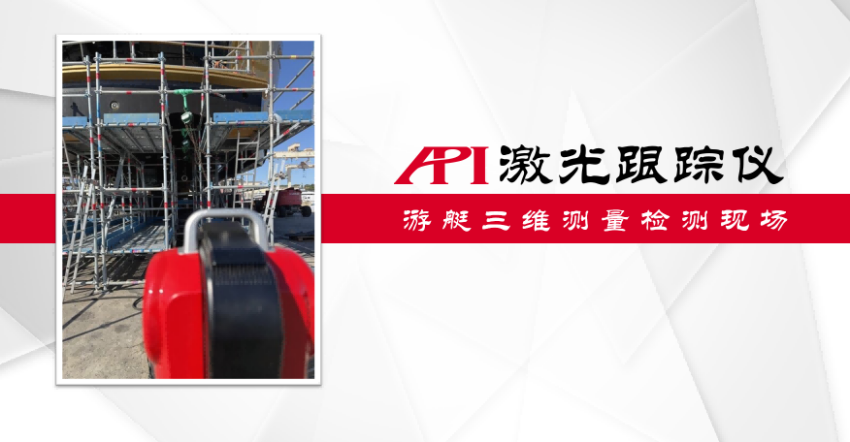
Figure 6: Measurement Site of This Case Study
Summary
Regular three-dimensional inspections of yachts represent a critical shift from "reactive repair" to "predictive maintenance," and the integration of API laser trackers has infused this process with high-efficiency, high-precision industrial measurement capabilities. Radian and iLT laser trackers, featuring micron-level precision coordinate systems, real-time deviation guidance, and flexible on-site adaptability, have completely transformed traditional workflows reliant on steel wires, dial indicators, and repeated disassembly. This technology has ushered yacht propulsion shafting, steering systems, and structural inspections into the digital era. Adopting API's 3D measurement solutions not only ensures superior sailing performance but also safeguards every voyage with comprehensive data, ensuring peace of mind and comfort at sea, making it an indispensable component of high-end yacht maintenance systems.
.

Figure 7: API Corporate Headquarters Building
About API
The API brand was founded by Dr. Kam Lau in Rockville, Maryland, USA, in 1987. As the inventor of the laser tracker and holder of multiple patents for globally leading measurement technologies, API is a pioneer in the field of precision measurement science. Since its inception, the company has been dedicated to the research, development, and manufacturing of precision measuring instruments and high-performance sensors for the mechanical manufacturing industry. Its products are widely applied in advanced manufacturing sectors worldwide, and API holds a leading position in high-precision standards for coordinate metrology and machine tool performance testing.
相关新闻:
Comprehensive Accuracy Rapid Assessment and Diagnosis of CNC Machine Tools Application Case of API
Regarding Rapid Testing of CNC Machine ToolsTime cost holds significant importan
Non-contact High-precision 3D Inspection of Construction Machinery Components API 9D LADAR (9D LiDA
The Importance of 3D Inspection for Construction Machinery ComponentsConstructio
High-Efficiency 3D Inspection of Large Steel Mill Equipment Application Case of API Laser Tracker
Importance of 3D Inspection for Large Steel Mill EquipmentLarge steel mill equip
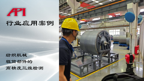
High-precision 3D Inspection of Textile Machinery Roller Components API Laser Tracker Application C
The Importance of 3D Inspection for Textile Machinery RollersRoller components a
Learn More:
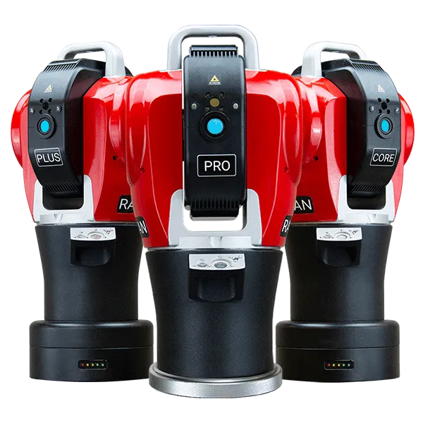
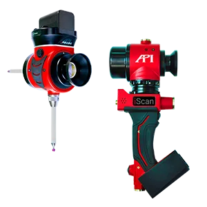
激光跟踪仪靶球&测头
Maximize laser tracker productivity with hand held and 激光跟踪仪主动靶标.
Learn More /laser-tracker-targets
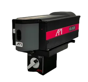
XD Laser CMM Calibration
The XD Laser is the only assessment system that can measure all 6 error parameters simultaneously in a single set-up
Learn More /xd-laser

API Reverse Engineering Service
Reverse engineering services include scan as-built parts to creation of a 3D digital point cloud and CAD Model.
Learn More /reverse-engineering/